
Here, the weld design becomes child's play. Using the specially developed material model "Orthotropic | Plastic | Weld (Surfaces)", you can calculate all stress components plastically. The stress τperpendicular is also considered plastically.
Using this material model you can design welds closer to reality and more efficiently.
Go to Explanatory Video
In the Timber Design add-on for RFEM, you can design members as well as surfaces according to Eurocode 5, SIA 265 (Swiss standard), CSA O86 (Canadian standard), or ANSI/AWC NDS (American standard); for example, cross-laminated timber, glued-laminated timber, softwood, mass timber, and so on.
Go to Explanatory Video.png?mw=640&hash=342149908caead326e60e26a2b5d05f7f46825cb)
Are you familiar with the Tsai-Wu material model? It combines plastic and orthotropic properties, which allows for special modeling of materials with anisotropic characteristics, such as fiber-reinforced plastics or timber.
If the material is plastified, the stresses remain constant. The redistribution is carried out according to the stiffnesses available in the individual directions. The elastic area corresponds to the Orthotropic | Linear Elastic (Solids) material model. For the plastic area, the yielding according to Tsai-Wu applies:
All strengths are defined positively. You can imagine the stress criterion as an elliptical surface within a six-dimensional space of stresses. If one of the three stress components is applied as a constant value, the surface can be projected onto a three-dimensional stress space.
If the value for fy(σ), according to the Tsai-Wu equation, plane stress condition, is smaller than 1, the stresses are in the elastic zone. The plastic area is reached as soon as fy (σ) = 1; values greater than 1 are not allowed. The model behavior is ideal-plastic, which means there is no stiffening.
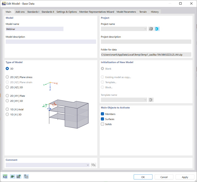
There are many options available for simple input and modeling. Your model is entered as a 1D, 2D, or 3D model. Member types such as beams, trusses, or tension members make it easier for you to define member properties. In order to model surfaces, RFEM provides you with various types, such as Standard, Without Thickness, Rigid, Membrane, and Load Distribution.
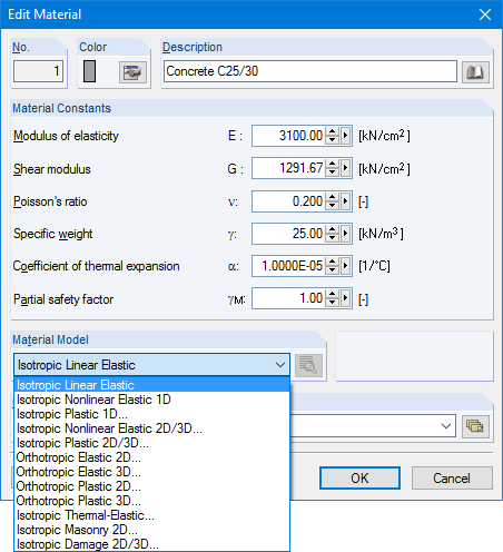
Furthermore, RFEM covers various material models, such as Isotropic | Linear Elastic, Orthotropic | Linear Elastic (Surfaces, Solids), or Isotropic | Timber | Linear Elastic (Members).
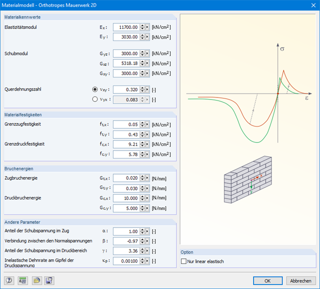
The material model Orthotropic Masonry 2D is an elastoplastic model that additionally allows softening of the material, which can be different in the local x- and y-directions of a surface. The material model is suitable for (unreinforced) masonry walls with in-plane loads.
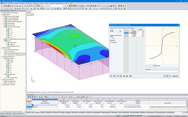
In RFEM, there is an option to couple surfaces with the stiffness types "Membrane" and "Membrane Orthotropic" with the material models "Isotropic Nonlinear Elastic 2D/3D" and "Isotropic Plastic 2D/3D" (add-on module RF-MAT NL is required).
This functionality enables simulation of the nonlinear strain behavior of ETFE foils, for example.
.png?mw=640&hash=688fdfc8af4828c08e9851cddb103a1e86cb899a)
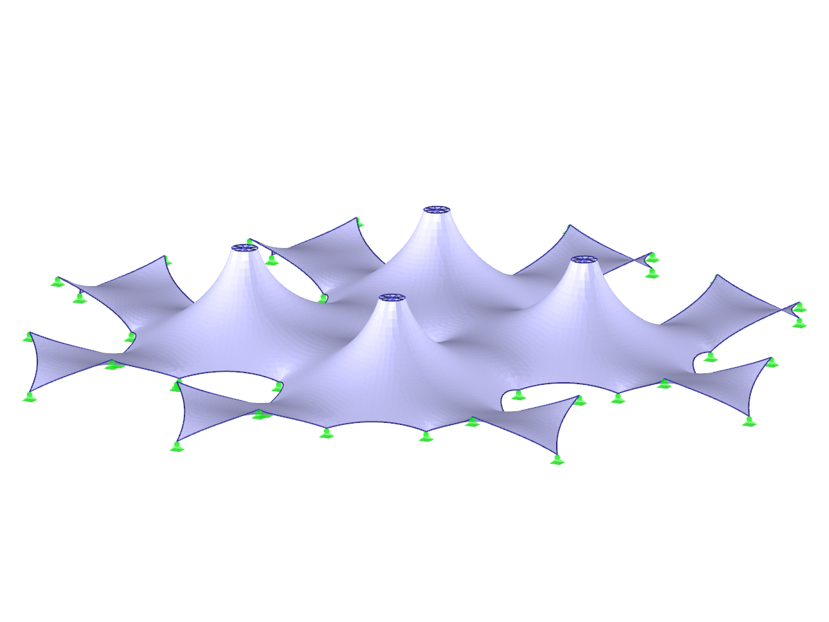
- Form-finding of:
- tension-loaded membrane and cable structures
- compression-loaded shell and beam structures
- mixed tension- and compression-loaded structures
- Consideration of gas chambers between surfaces
- Interaction with supporting structure (substructure design according to various standards)
- Surfaces as a 2D and members as a 1D element
- Definition of different prestress conditions for surfaces (membranes and shells)
- Definition of forces or geometrical requirements for members (cables and beams)
- Consideration of individual loads (self‑weight, inner pressure, and so on) in the form‑finding process
- Temporary support definitions for the form-finding process
- Automatic preliminary form-finding of membrane surfaces (more information...)
- Definition of isotropic or orthotropic material for structural analysis
- Optional definition of free polygon loads
- Transformation of form‑found shape elements into NURBS surface elements
- Possibility of combined form-finding by integration of preliminary form-finding
- Graphical evaluation of the new form using colored coordinates and inclination plots
- Complete documentation of the calculation including user-defined adaptive evaluation figures
- Optional export of the FE mesh as a DXF or Excel file
The following material models are available in RF − MAT NL:
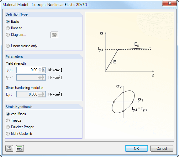
Isotropic Plastic 1D/2D/3D and Isotropic Nonlinear Elastic 1D/2D/3D
You can select three different definition types here:
- Basic (definition of the equivalent stress under which the material plastifies)
- Bilinear (definition of the equivalent stress and strain hardening modulus)
- Diagram:
- Definition of polygonal stress-strain diagram
- Option to save / import the diagram
- Interface with MS Excel
Orthotropic Plastic 2D/3D (Tsai-Wu 2D/3D)
This material model allows the definition of material properties (modulus of elasticity, shear modulus, Poisson's ratio) and ultimate strengths (tension, compression, shear) in two or three axes.
Isotropic Masonry 2D
It is possible to specify the limit tension stresses σx,limit and σy,limit as well as the hardening factor CH.
Orthotropic Masonry 2D
The material model Orthotropic Masonry 2D is an elastoplastic model that additionally allows softening of the material, which can be different in the local x- and y-directions of a surface. The material model is suitable for (unreinforced) masonry walls with in-plane loads.
Isotropic Damage 2D/3D
Here, you can define antimetric stress-strain diagrams. The modulus of elasticity is calculated in each step of the stress-strain diagram using Ei = (σi -σi-1 )/(εi -εi-1 ).
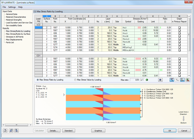
- General stress analysis
- Graphical and numerical results of stresses and stress ratios fully integrated in RFEM
- Flexible design with different layer compositions
- High efficiency due to few entries required
- Flexibility due to detailed setting options for basis and extent of calculations
- A local overall stiffness matrix of the surface in RFEM is generated on the basis of the selected material model and the layers contained. The following material models are available:
- Orthotropic
- Isotropic
- User-defined
- Hybrid (for combinations of material models)
- Option to save frequently used layer structures in a database
- Determination of basic, shear, and equivalent stresses
- In addition to the basic stresses, the required stresses according to DIN EN 1995-1-1 and the interaction of those stresses are available as results.
- Stress analysis for structural surfaces including simple or complex shapes
- Equivalent stresses calculated according to different approaches:
- Shape modification hypothesis (von Mises)
- Shear stress hypothesis (Tresca)
- Normal stress hypothesis (Rankine)
- Principal strain hypothesis (Bach)
- Calculation of transversal shear stresses according to Mindlin or Kirchhoff, or user-defined specifications
- Serviceability limit state design by checking surface displacements
- User-defined specifications of limit deflections
- Possibility to consider layer coupling
- Detailed results of individual stress components and ratios in tables and graphics
- Results of stresses for each layer in the model
- Parts list of designed surfaces
- Possible coupling of layers entirely without shear
Structures are entered as 1D, 2D, or 3D models. Member types such as beams, trusses, or tension members facilitate the definition of member properties. For modeling surfaces, RFEM provides For example, the types Standard, Orthotropic, Glass, Laminate, Rigid, Membrane, and so on, are available.
Furthermore, RFEM can select among the material models Isotropic Linear Elastic, Isotropic Plastic 1D/2D/3D, Isotropic Nonlinear Elastic 1D/2D/3D, Orthotropic Elastic 2D/3D, Orthotropic Plastic 2D/3D (Tsai-Wu 2D/3D), and Isotropic Thermal -elastic, Isotropic Masonry 2D, and Isotropic Damage 2D/3D.